| Turnbuckle Construction Pictures |

| Fuselage |
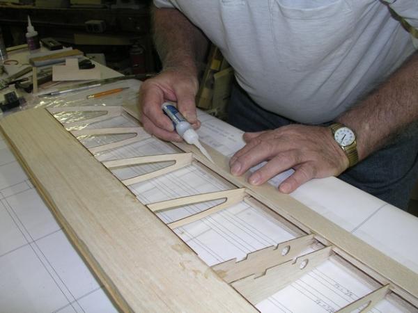
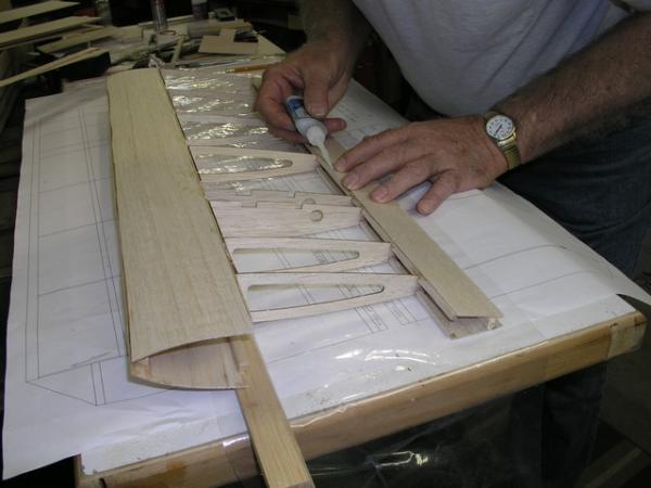
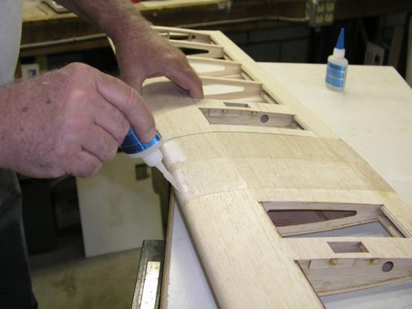
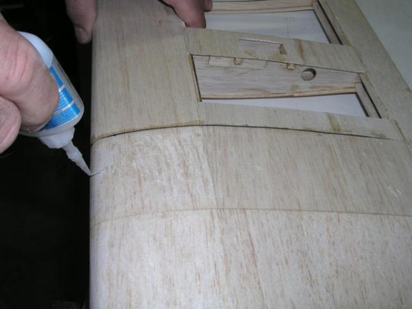
| Wing |
| Ailerons |
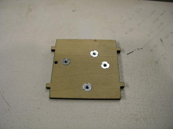
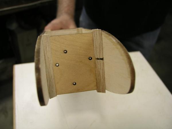
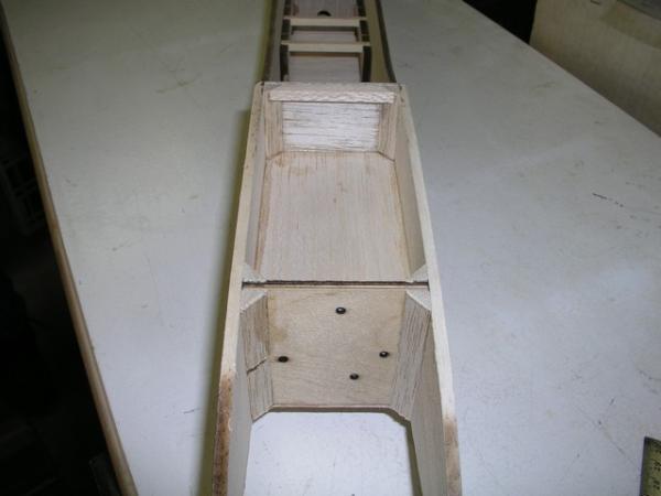
| Rear view of firewall showing blind nuts installed |
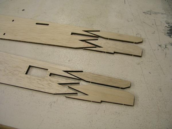
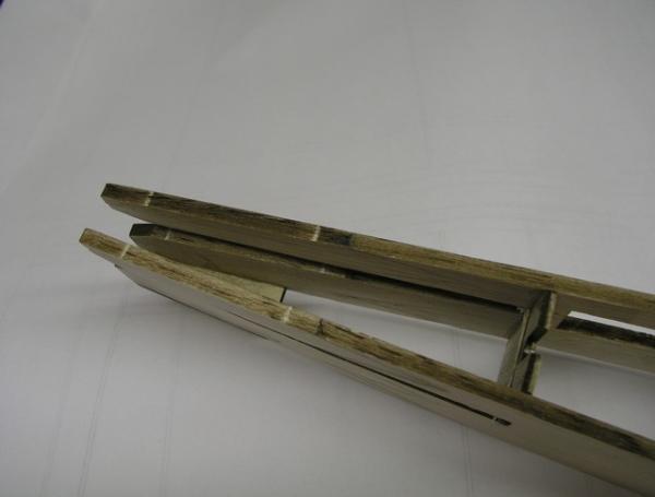
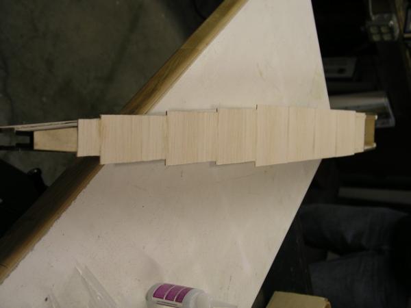
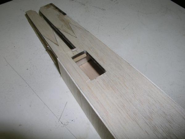
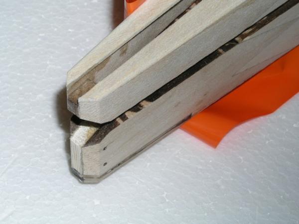
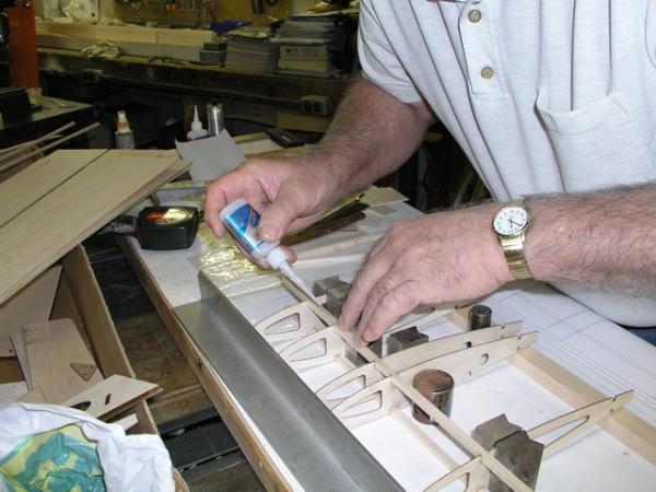
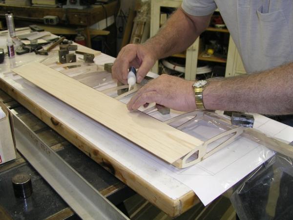
| Use medium ca to join fuelage rear pieces |
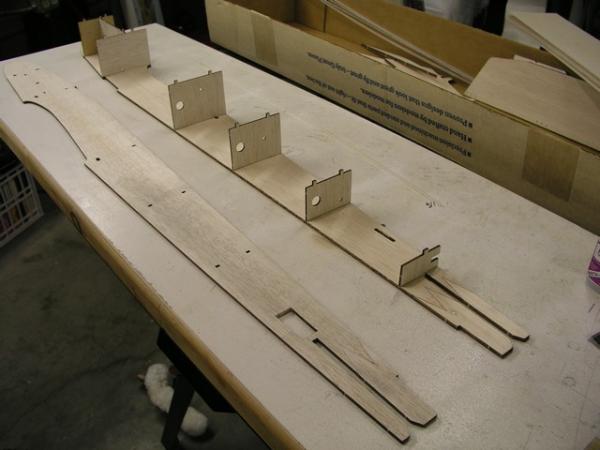
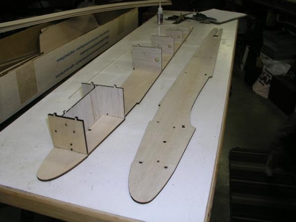
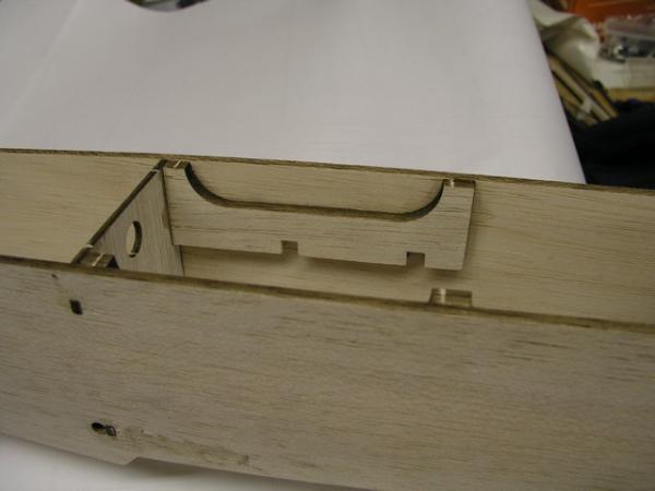
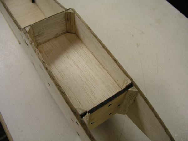
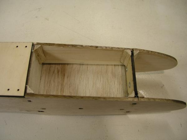
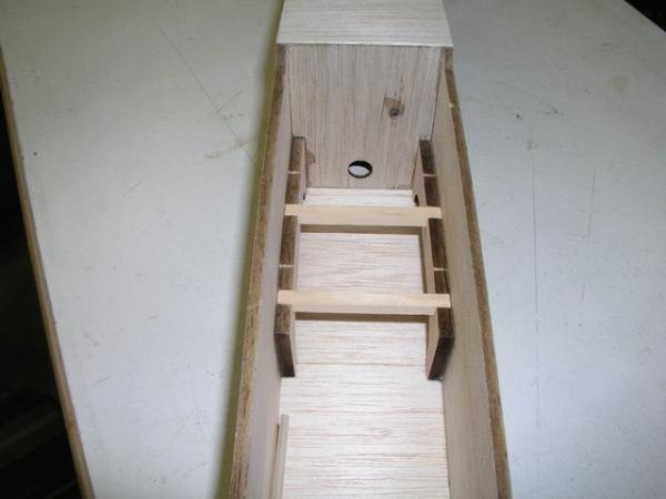
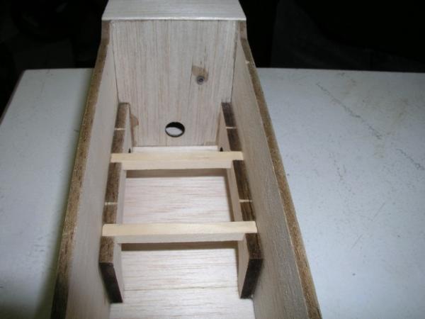
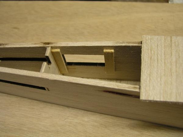
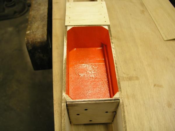
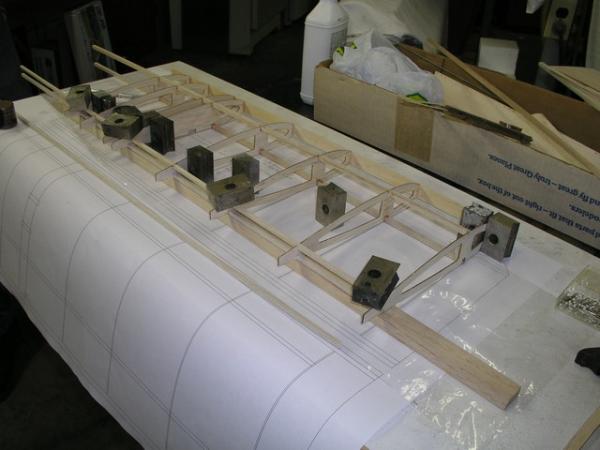
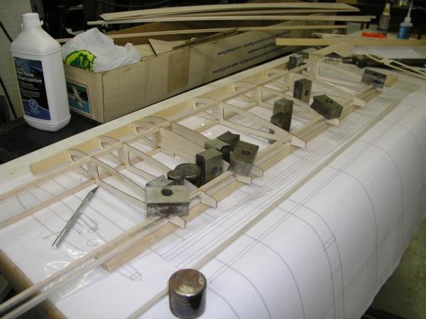
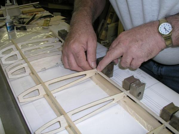
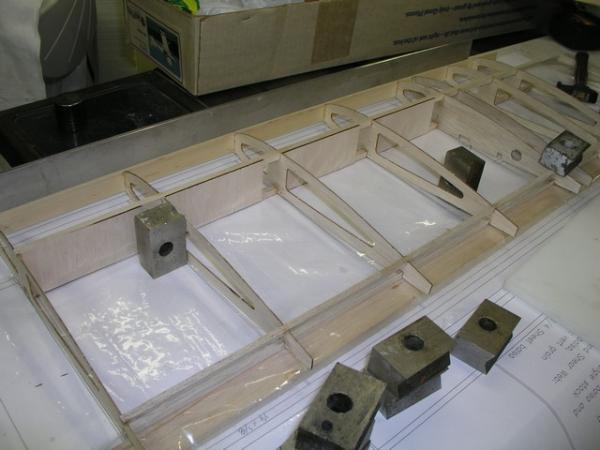
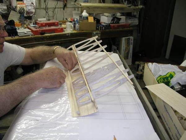
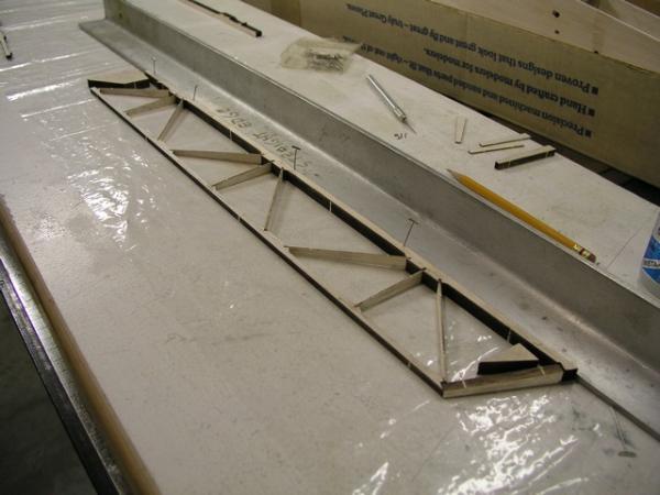
| Formers and tank floor test fit. DO NOT GLUE YET!!! |
| Formers and tank floor test fit. DO NOT GLUE YET!!! |
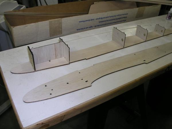
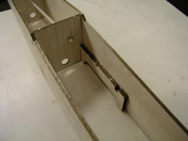
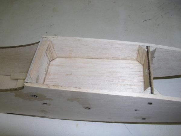
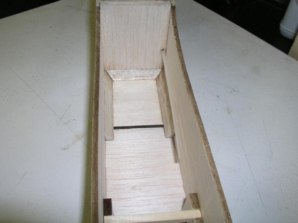
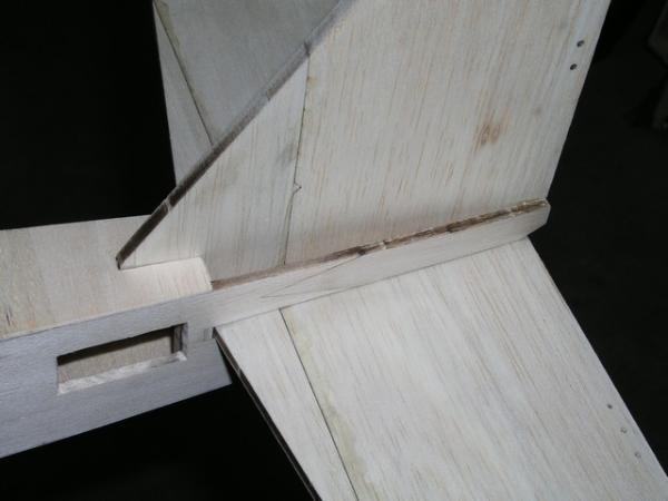
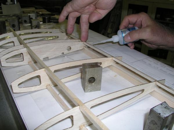
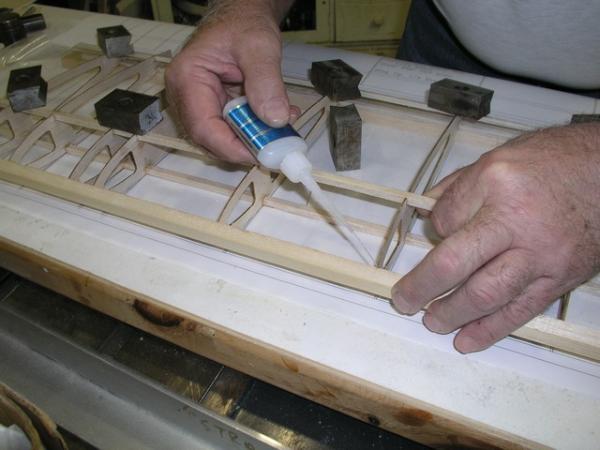
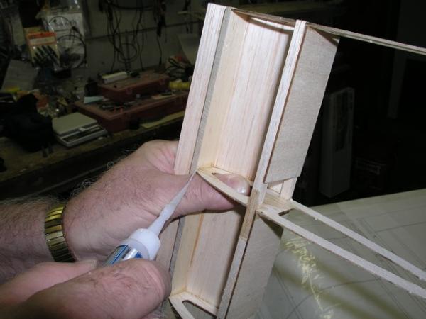
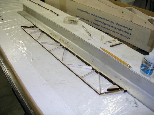
| Put left side in place on firewall, F1 and F2 and tank floor. Make sure all aligning tabs are fully inserted (some of the tabs may extend past the outer fuselage sides) and while pressing sides against the formers and tank floor apply thin CA to all Firewall tank floor and F1 and F2 interfaces. |
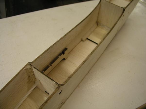
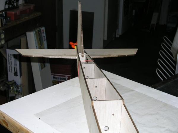
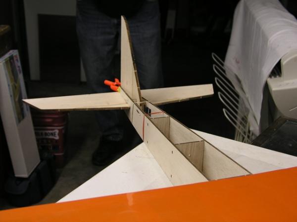
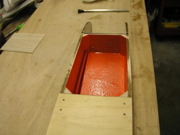
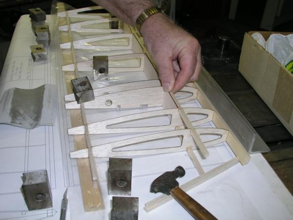
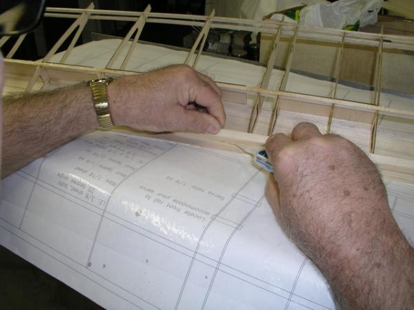
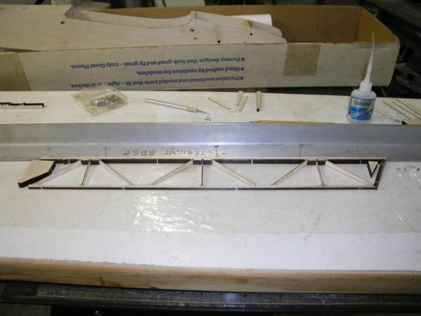
| Fully insert the tabs of formers F3, F4 and F5 into both fuselage sides. Locate the horizontal stabilizer in it's slot and place a straight edge across the wing saddle. Check the fuselage is not twisted by ensuring that the stabilizer and straight edge are parallel to one another. Locate the plywood tail wheel mount and med CA one side of it in place so that it lines up with the outside surface of the fuselage side. Then med CA the other side of the ply mount so that the outer surfaces line up. |
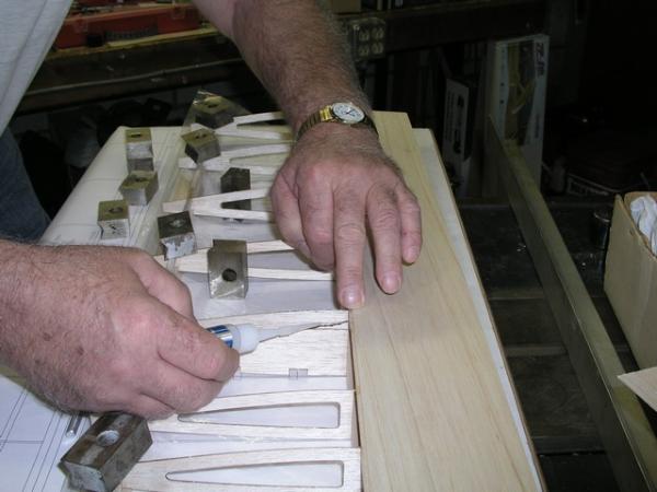
| Make sure that the fuselage is straight and the tabs are fully inserted, then apply thin CA on the outside surfaces of the fuselage to the tabs of F3, F4 and F5 to tack them in place. Recheck fuselage alignment and when satisfied, apply thin CA to fully glue those formers in place. Hopefully at this time the fuselage is straight and the horizontal stabilizer will be parallel to the wing saddle. |
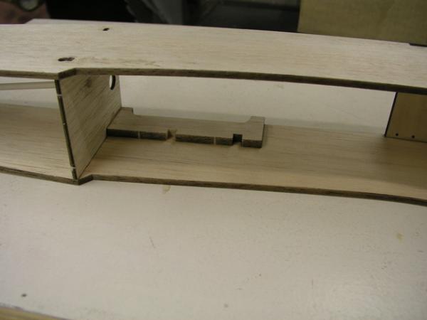
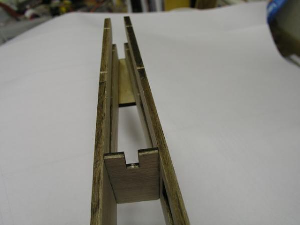
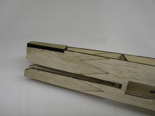
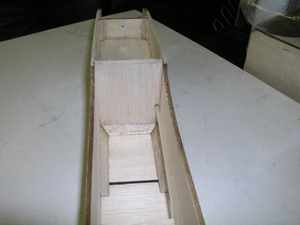
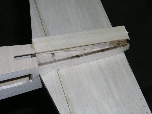
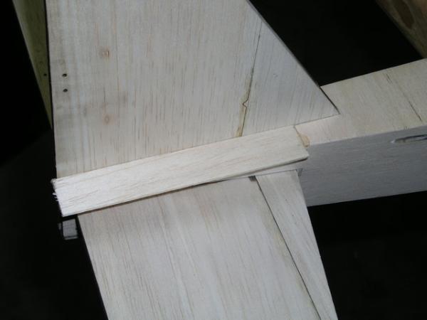
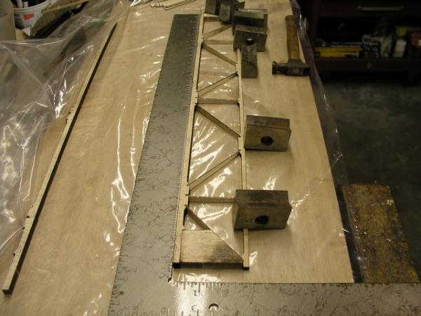
| Not shown, but now is the time to fit the tapered lower fuselage joiner in place. It's location lines up with the rear of the fuselage sides, the plywood tail wheel mount and the lower edge of the stabilizer cutout. Use medium CA to glue it into place. |
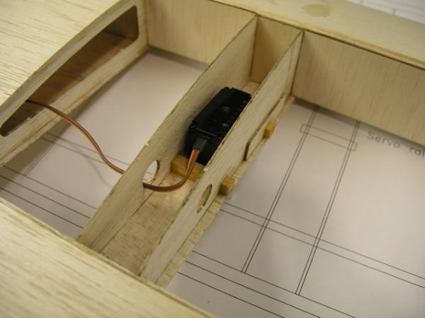
| Now is the time to med CA the landing gear mount in place. After deciding what servos you are going to use for the elevator and throttle, the fuselage servo rail supports must be modified to accomodate these servos. Thin Ca is used to glue them in place. (Make sure you install them on the correct sides!) |